It is essential to choose the correct power factor correction panel for your system. In fact, as you already know, there must be a balance between the types of power present in your network, otherwise you risk an excess of reactive energy (which is charged extra by utility companies).
The first step is the measurement of the cosΦ
There are several ways to measure your cosΦ:
- The first, which is also the simplest, is to check your electricity bill. Many utility electric companies indicate this parameter among other information.
- The second is to use a power analyzer. This solution is certainly the most useful. In fact, in addition to the indication of your cosΦ, a power analyser will provide you with all the information regarding your network, such as the presence of harmonics, the consumption of electricity and the phase balance.
- The third is to use a power factor meter. In this case the instrument will directly indicate the PF (power factor) value. As previously explained, the PF = cosΦ if there are no non-linear loads (and hence harmonics) in your network.
- The fourth way is to use reactive energy meters. In this case you will have to make some calculations, since the indicated values are only relative to energy.
To make it short, you have to consider four values: two at the beginning of the work cycle, and two at the end of the work cycle. The data to take in consideration are active and reactive energy. Here is the formula to calculate the cosΦ:
CosΦ= cos(tan^-1((Eqf – Eqi)/(Epf – Epi))
Where:
- Eqf is reactive energy at the end of work cycle.
- Eqi is reactive energy at the begging of work cycle.
- Epf is active energy at the end of work cycle.
- Epi is active energy at the begging of work cycle.
The second step is the calculation of the necessary reactive power Q(c)
In order to calculate the reactive power that is necessary to improve power factor, it is important to know the active power of the load, the actual and the desired cosΦ.
We have already found the present cosΦ.
The desired cosΦ value depends on the electric company. In fact, this value can range from 0.90 to 0.97. Gruppo Energia automatic regulators are normally set to reach the cosΦ value of 0.99 in our own capacitor banks. The active power of the machinery (load) to be compensated is normally indicated on their information plate.
Once we have all three parameters available, we use the following formula to determine the reactive power:
Q(c) = P x k
Where:
- Q(c) is the necessary reactive power (kVar).
- P is active power of the load to be compensated (kW).
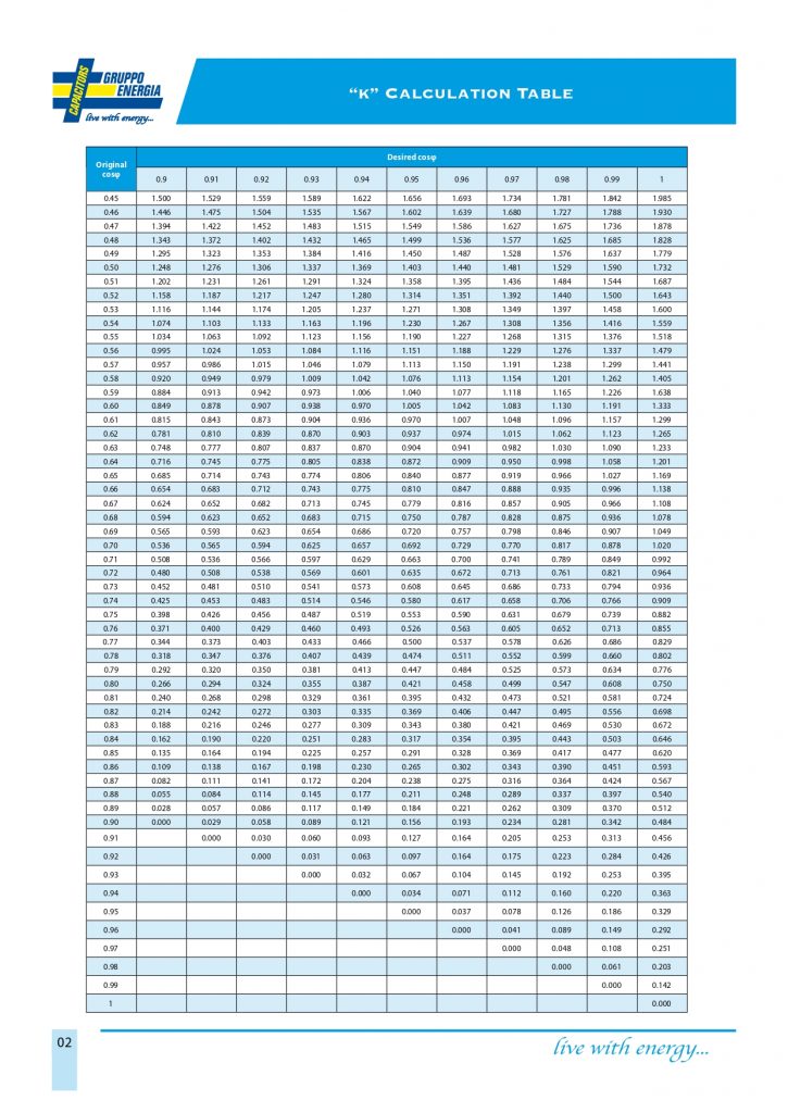
- k is the conversation coefficient in the table you can find below. You can find it by crossing the value of the actual cosΦ and the desired cosΦ.
Calculation example:
Active power (load power) P: 100 kW
Actual cosΦ: 0,55
Desired cosΦ: 0,99
Coefficient from the table: 1,376
Q(c) = 100 x 1,376 = 137,6 kVar
As you can see, the reactive power to be compensated is 137,6 kVar, which can be approximated to 150 kVar considering that the loads might slightly increase in the future.
The third step is to choose between fixed or automatic correction
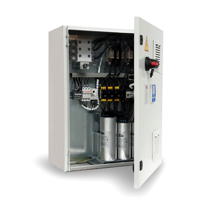
If your system is quite small, we normally suggest a fixed power factor correction bank. In this case the power of capacitors is fixed to supply the constant reactive power to the exiting load. Even the load should not be changed.
When the loads that need to be compensated are variable (this currently happens in most cases), we suggest an automatic power factor correction.
The total power of the capacitor bank is divided in steps. These steps are controlled by a regulator which constantly analyses the network and operates the step with suitable power, in order to compensate the load present at that moment. Here is a formula that can help you choose:
(Q(c) / S(n)) * 100 = %
Where:
Q(c) is the necessary reactive power (kVar).
S(n) is apparent power of installed transformer (kVA).
If the result is < 15% we suggest fixed compensation.
If the result is ≥ 15% we suggest automatic compensation.
The fourth step is deciding if you need a standard, heavy duty or detuned capacitor bank
The most correct and accurate way to do that is by using a network analyser, which will show you in detail in what condition your network is and how much it is afflicted by harmonics. In this case you need to check the THD(i)% (total harmonic current distortion) and THD(u)% (total harmonic voltage distortion) values. Measurements must be made at full load and without connected capacitors at the transformer secondary.
If THD(i)% ≤ 5% a standard PFC capacitor bank is usually enough;
If 5% < THD(i)% ≤ 10% a heavy duty PFC capacitor bank is suggested;
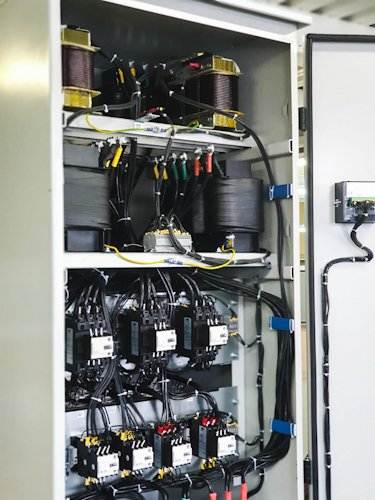
If 10% < THD(i)% ≤ 20%, the best solution would probably be a heavy duty PFC capacitor bank with suitable harmonic detuned reactors;
If THD(i)% > 20% we recommend to install an active harmonic filter;
If THD(u)% ≤ 3% we normally suggest a standard PFC capacitor bank;
If 3% < THD(u)% ≤ 4% you should probably install a heavy duty PFC capacitor bank;
If 4% < THD(u)% ≤ 7% we suggest a heavy duty PFC capacitor bank with suitable harmonic detuned reactors;
If THD(u)% > 7% we recommend the installation of an active harmonic filter.
Finally, if both THD(I) and THD(U) are measured and do not result in the same type of power factor correction, you must chose the most rigorous solution. For example, if we get the following values from the network analyser:
THD(I) = 15% – we normally suggest using a heavy duty PFC capacitor bank with suitable harmonic detuned reactors
THD(U) = 8% – we recommend installing an active harmonic filter
…the most critical parameter is the THD(U)=8%, so the best solution would be choosing an active harmonic filter.
If you don’t have a network analyser, you can use the following formula to calculate the percentage of non-linear loads in your network:
(S(h) / S(n)) * 100 = % N(LL) of active harmonic filter is recommended.
S(h) is the total apparent power of all non-linear loads in your network (kVA).
S(n) is the apparent power of installed transformer (kVA).
N(LL) is the percentage of non-linear loads in your network.
If N(LL) < 15% we normally recommend a standard PFC capacitor bank.
If 15% < N(LL ) < 25% you may want to consider a heavy duty PFC capacitor bank.
If 25% < N(LL) < 50% our suggestion is a heavy duty PFC capacitor bank with suitable harmonic detuned reactors.
If N(LL) ≥ 50% we recommend installing an active harmonic filter.
This will allow you to calculate the percentage of non-linear loads in your network. Note: the S(h)/S(n) rule is valid for a THD(I) of all the harmonic generators < 30% and for pre-existing THD(U) < 2%.
If these values are exceeded, you need to perform a harmonic analysis of the network.
Make sure to share this post with your colleagues if you found it useful, and let us know how we can help you further!
