What are linear and non-linear loads?
Today we would like to continue our conversation about Power Factor Correction and our tips to improve it. Make sure to read the first part, if you haven’t already!
Previously we wrote about linear and non-linear loads, but we haven’t really explained what they are.
The main difference between them is the way they draw current from the mains power supply waveform.
In case of linear loads, the relationship between voltage and current waveforms is sinusoidal and the current is proportional to the voltage at any time.
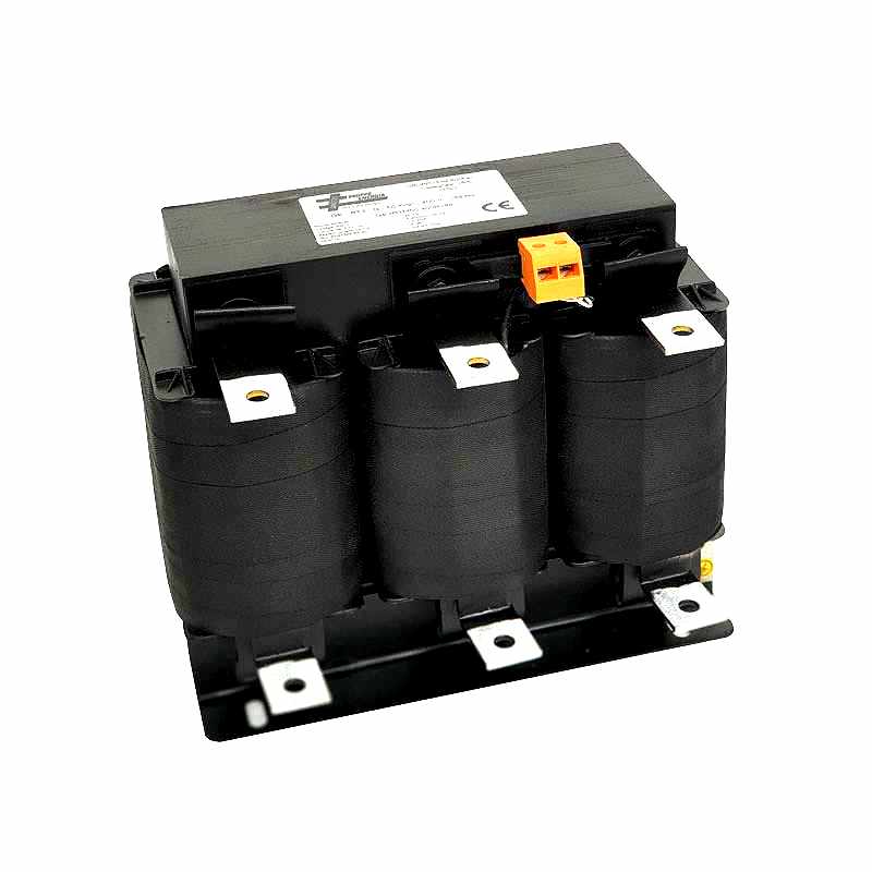
Linear loads are for example engines, transformers, reactors or capacitors.
On the contrary, in the case of non-linear loads, the current is not proportional to the voltage and it fluctuates according to an alternating load impedance.

Non-linear loads can be motor controllers, inverters, welding equipment, MRI scanner, rectifiers, UPS systems, computers, printers, TVs, etc.
Unfortunately, non-linear loads draw in currents in abrupt short pulses. These pulses distort the current waveforms, which in turn generates harmonics, that can lead to power problems. Power problems can affect both the distribution system equipment and the loads connected to it.
In some countries, if your network is affected by harmonics you will have to pay penalties that are added to your electricity bills.
A good network analyser will easily provide you with more information about your network and evaluate your harmonic distortion. This will help you choose the most suitable equipment for your needs.
But how to solve power problems?
Linear and non-linear loads need a personal approach.
In fact, linear loads are happy with a simple romantic dinner (or standard power factor correction capacitor bank).
On the contrary, non-linear loads are high-maintenance and require a starred Michelin restaurant in order to be happy (i.e. the use the detuned power factor correction panel with harmonic reactors).
In case your need is to completely get rid of harmonics and make the waveform perfect and sexy, the solution is to use an active harmonic filter.
Pay attention that in some cases your system may be in the opposite situation to what is described in our previous post . That means that you have an excess of capacitive load. In this case, you will have to opt for inductive compensation panels equipped with reactors instead of capacitors.
What are Cos Phi (Cos φ) and Power Factor (PF)?
These two parameters are at the same time similar and different from each other. In fact, in networks with linear loads, power factor and cos (φ) correspond. They indicate the ratio between active (working or actual) power, measured in kW (kilowatts) and apparent power, measured in kVA (kilovolt amperes). We can sum it up with the following formula:
Cos Phi (at 50 Hz) = Active power (kW) / Apparent power (kVA) = Power factor
You can calculate the apparent power by multiplying V x A = kVA, and this corresponds to the amount of power used to run your machinery and equipment during a certain period.
In networks with non-linear loads, the situation is a little more complicated, due to the presence of harmonics. In fact, power factor remains the ratio of kW (active power) to kVA (apparent power), but the kVA now has a harmonic component as well.
Finally, true power factor (tPF) becomes the combination of displacement power factor (dPF) and distortion power factor (hPF). Displacement PF is still equal to cos (φ), with (φ) being the angle between the fundamental current and voltage. Displacement PF can be either leading (if there is a prevalence of the capacitive load) or lagging (if the load is mainly inductive).
For example, the displacement power factor of a variable speed drive will be near 1, but its true power factor often ranges between 0.7 and 0.8, unless you use harmonic mitigation equipment. Therefore, we can translate all this with the following formula:
True power factor (tPF) = Displacement power factor (cos phi) x Distortion power factor.
We will soon provide you with more information about power factor correction, so stay tuned! Share this post with your colleagues!
If you have any specific questions, contact us and our engineering team will be happy to answer.